Blog – What is Foreign Object Detection in Wireless Charging, Anyway?

What is Foreign Object Detection in Wireless Charging, Anyway?

Nobody can argue that Wireless Charging is an incredibly convenient way to keep our favorite handheld devices charged up, and to provide some remedy for battery anxiety.  Wireless charging is (almost) everywhere nowadays — in our phones, in our cars, in our airports, in our restaurants and coffee shops, and soon to be in places we haven’t even thought of yet.  But is it safe?  We have seen internet articles about wireless charging shortening the life of your smartphone’s battery, or other ways wireless charging can harm your device.  But unfortunately, those articles are not written by people who understand wireless charging, and are false and misleading.  (Spoiler:  There is no difference in charging your phone from a wire or from wireless — it’s just another way of getting energy.)

Back to our question:  Is wireless charging safe?  The answer, of course, is a resounding “yes”, provided it is done correctly.  One of the biggest safety topics to understand in a modern-day wireless charger is how to prevent the wireless charger from heating metal objects to unsafe levels.  Because the frequency used by the wireless charger is very effective at heating metal objects, it is up to us as system designers to ensure that any stray metal objects, such as wayward coins, that present themselves in the middle of a charging session are not a cause for alarm (as in “fire alarm”).  In order to protect ourselves from these “foreign” metal objects, we try to detect this safety threat with something called “Foreign Object Detection”, or FOD.

Historically, ever since the introduction of Foreign Object Detection (FOD) methods in the Wireless Power Consortium Qi (pronounced “chee”) standard, the general public has had a misunderstanding of what FOD really means.

If a random person is asked what FOD must do, in most cases the answer would be that if a coin is placed on the transmitter surface, the transmitter should indicate the presence of a foreign object. This is basically the functionality of a metal detector.

In practice most receivers like phones and battery packs have metal elements around the receiving coil. User experience can be negatively affected if these metal elements are wrongly classified as foreign objects. According to the Qi specification, a foreign object is detected only after a Qi receiver is placed on the transmitter surface, information is exchanged between the two devices and a decision is made about the foreign object presence based on the estimation of how much power would actually be dissipated into the foreign object during power transfer. It is perfectly acceptable to have an object on the transmitter surface during power transfer if it does not heat above certain thresholds.


OBJECT PLACEMENT ON THE TRANSMITTER SURFACE

The most popular method to detect the presence of an object on the transmitter surface is the Direct Q Measurement. It monitors for changes to the quality factor (Q factor) of the transmitter coil or for changes in its inductance or resistance. Other methods that detect the presence of objects on the transmitter coil can be based on change in capacitance, light reflection or transmission, changes in weight/pressure, resonance at 1MHz, metal detectors using auxiliary coils, etc.

The Qi specification has an informative section reserved for these mechanisms. The resonance shift method is already described and is related to the change in quality factor. The fact that a resistance change is also induced by most (but not all) receivers can be used to improve the detection of the object but it is not enough to determine if the presumed foreign object would actually absorb enough energy during power transfer to cause a significant increase in its temperature.


CONFUSION BETWEEN THE DIRECT Q MEASUREMENT AND THE EXISTING PRE-POWER FOD METHOD

These values are measured when a receiver is placed on a MP-A1 transmitter coil and they are reported by the receiver during the negotiation phase.

The transmitter may not use a MP-A1 coil and in that case its measurements of Q and resonant frequency must be converted from the actual transmitter coil to how they would look like on the MP-A1 coil before a decision can be made regarding the mismatch between the measured values and the reported values from the receiver.

The Qi specification has a high-level description of the pre-power FOD methods but the mechanism used to calculate the Q factor seen by a MP-A1 coil is not provided.

The direct measurement of the transmitter coil quality factor without a receiver present can at most inform the transmitter of the existence of metallic objects on the charging surface, and the transmitter can use this data to inform the user to clear these objects before placing the receiver on the surface. This method can also be used after a confirmed FOD event and subsequent removal of power.  In that case, the transmitter uses this method to ensure the user has removed all objects from the charging surface before allowing the receiver to be placed to restart charging.

This method alone cannot determine if the metallic object will consume sufficient power to heat the object, but it can be used in combination with other power loss methods to educate the user to always remove all metal objects from the transmitter surface before/during/after charging.

Confusing?  The key is in the name of the action:  Foreign Object Detection.  It’s one thing to detect a metal object, but it’s a whole different ballgame to determine if that object will lead to an unsafe situation if we charge a phone while that object is present.  As a charger, what you want to do is charge a user’s battery — that is, after all, the reason you exist.  Therefore a charger must have a robust and deterministic plan for deciding which objects are clearly unsafe, and which objects can still be present during a charging cycle without cause for alarm.  If I am too conservative, then nobody gets to charge.  But if I am too lenient, then somebody gets burned (maybe literally).  Striking the right, and safe, balance is the art of good transmitter design.

Emanuel Stingu Spark Connected, CTO

“It is perfectly acceptable to have an object on the transmitter surface during power transfer if it does not heat above certain thresholds.” – Emanuel Stingu, Chief Technology Officer at Spark Connected.

About Spark Connected

Spark Connected | powering the world, wirelessly

Spark connected is an industry leader specializing in multiple advanced and safe wireless power technologies that benefits a wide variety of applications in the Automotive, Industrial, Infrastructure, Medical, Telecom and Security, Robotics, Factory Automation, IOT, Smart Home, and Consumer markets.

Spark is transforming wireless power delivery and intelligent battery charging with innovative platforms, disruptive technology and breakthrough products enabling an enhanced user experience for all. The company specializes in Product Development and Engineering Solutions with a team of passionate innovators with decades of combined deep domain expertise.

Spark Connected is a Full Member of the Wireless Power Consortium.

Please forward inquiries to:
Marina Wolf/Ruwanga Dassanayake
(972) 855-8026
sales(at)sparkconnected.com


Blog – The Leap Beyond 15W Wireless Charging

Powered By Spark - Wireless power and wireless charging blog

INTRODUCTION

Since the public announcement of near-field coupled magnetic-field based resonant wireless power transfer (WPT) in 2006, wireless charging technology has been undergoing significant development. Since then standards bodies such as Qi Wireless Power Consortium (WPC) as well as PMA/Airfuel Alliance have been formed, among which, Qi WPC has been the main driving force in advancing and establishing the standards for the WPT and wireless charging.

Different wireless chargers including 5W legacy and 15W next-generation have been certified and utilized in the market. With the success at these power levels the industry is leaping for the next big step to hit the market with the power levels of 30W, 45W, 60W, and beyond.  The application for these power levels could involve laptops, drones, autonomous robots, power tools, etc.

OPERATION PRINCIPLES

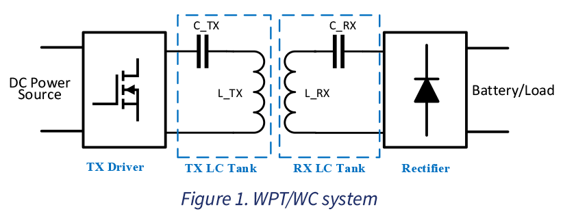
The near-field wireless power transfer operates based on the magnetic-filed coupling of the transmitter (TX) and receiver (RX) coils. The magnetic field is stablished with alternative current (ac) at different frequencies including radio frequency (RF), resonant, or near resonant frequencies, where the latter is designed for inductive charging. Figure 1 depicts a near-field coupled WPT/WC system. Depending on the switching frequency of the TX driver as well as LC tanks resonant frequency the system could be designed to operate in one of the three aforementioned operation modes.

The Leap Beyond 15W Wireless Charging - WPT/WC system by Malek Ramezani
The TX driver output is an ac voltage with a fundamental frequency at which the system is designed for. This voltage supplies the TX LC tank with an ac current establishing a magnetic field in the TX coil. When a wireless power receiver is at the presence of this filed, the coupling between the TX and RX coils induces an ac voltage across the RX coil which yields to an ac voltage at the input of RX rectifier. This ac voltage is then rectified to either charge a battery or supply a load.

The deceptively simple appearance of this system has demanded enormous effort from EE engineers to improve its efficiency and reliability in competition with the wire-based chargers. Although, 5W WC systems have shown a promising dependability and met the market’s demand, the 15W is still challenging the technology leading companies and agencies. The challenge is not only optimizing the  systems for a higher efficiency but also their reliability is highly dependent on the communication system between TX and RX. The communication system provides a negotiation mechanism through which the TX and RX establish a power transfer agreement. The traditional communication between the TX and RX in the 5W systems has been based on a low-bandwidth in-band communication where the message is modulated on top of the power signals at its origin and then is demodulated from the power signals at its destination. The in-band modulation is usually implemented through amplitude shift keying (ASK), frequency shift keying (FSK), or phase shift keying (PSK), or a combination of these methods. It can be conceived that this communication method could be affected by the dynamics of the power signal. Therefore, the gateway to the higher reliability of WC systems at power levels of 15W  and beyond is  enhancing their communication robustness independent from the power signals dynamics and therefore improving overall system reliability. The possible solution could be the out-of-band communication with high bandwidth and bit rate such as Bluetooth, NFC, or similar technologies.

Development of higher power WC systems for applications where simultaneous power and data transfer are needed could be a revolutionary transition to a cord-less world. The  application of these WCs in consumer electronics, especially in laptops would be the beginning of an integrated wireless charging and data transfer unit. In this outlook a transmitter unit, e.g., a laptop docking station at the power levels of 45 – 200 Watts could be utilized as both power and data transfer wireless link. At the front-line of battle between the wired and wireless world a technology leader such as Spark Connected is fulfilling its mission towards Powering the world, wirelesslyby developing the most advance and reliable 45 – 200  Watts  WPT and WC systems.

Malek Ramezani - WPC Co-Chair and Senior Power Electronics Systems Engineer at Spark Connected

Malek Ramezani

  • Senior Power Electronics Engineer
  • PhD in Electrical Engineering from The University of Alabama
  • Co-chair for Foreign Object Detection (FOD) at the Wireless Power Consortium (WPC/Qi)

About Spark Connected

Spark Connected | powering the world, wirelessly

Spark connected is an industry leader specializing in multiple advanced and safe wireless power technologies that benefits a wide variety of applications in the Automotive, Industrial, Infrastructure, Medical, Telecom and Security, Robotics, Factory Automation, IOT, Smart Home, and Consumer markets.

Spark is transforming wireless power delivery and intelligent battery charging with innovative platforms, disruptive technology and breakthrough products enabling an enhanced user experience for all. The company specializes in Product Development and Engineering Solutions with a team of passionate innovators with decades of combined deep domain expertise.

Spark Connected is a Full Member of the Wireless Power Consortium.

Please forward inquiries to:
Marina Wolf/Ruwanga Dassanayake
(972) 855-8026
sales(at)sparkconnected.com
Ken Moore, CEO at APEC 2018

Ken Moore, wireless power solutions at APEC 2018, compatible with the Qi wireless charging protocol.

In this video Ken from Spark Connected gives a quick overview on their latest wireless power solutions at APEC 2018 in San Antonio, Texas. The solution includes all components necessary to create a complete wireless charging system, compatible with the Qi wireless charging protocol.

Ken Moore, CEO at the 2018 global event Applied Power Electronics Conference (APEC)
San Antonio, Texas

Wireless Charging: Complete Solutions With Dedicated Microcontrollers, Mosfets, Drivers And IP Software

Complete Solutions With Dedicated Microcontrollers

Published by ELE Times

There are a number of challenges for designers of wireless charging products. In addition to issues associated with the magnetics, they have to deal with efficiency, mechanical packaging and electromagnetic interference (EMI). However, with optimized components and if certain basic criteria like the alignment of charger and device, size of coils and distance between coils relative to the size of the coil are met, then a good coupling factor can be achieved, and power can be transferred with high efficiency. In addition, metallic foreign objects (such as coins and keys) may interfere with the charging and have to be detected (FOD, Foreign Object Detection).

The technology is moving from transmitters that charge single devices to transmitters that can charge several devices simultaneously, using either multi-coil inductive or resonant charging.

Key to the success of the overall wireless charging ecosystem will be the adoption of the technology into applications beyond smartphones, such as wearables, medical instruments, robots, drones and point of sale terminals. Infineon’s array of wireless charging solutions range from low-power support for charging using very small coils and multi-device charging, to a flexible high-power offering that is backward compatible for lower-power products such as smartphones. These types of charging experiences are not supported by existing smartphone charging solutions.

Inductive and resonant

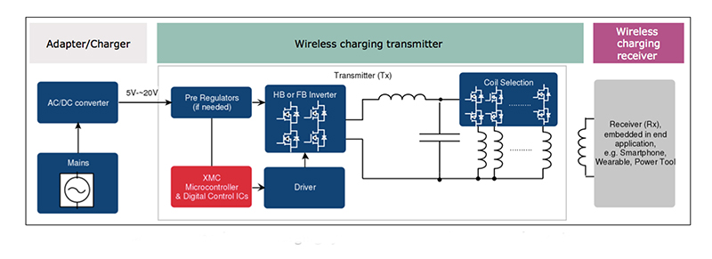
Wireless charging solutions typically have three key elements; the adapter/charger, the transmitter and the receiver. The adapter connects to the mains supply and powers the transmitter, usually with a regulated DC voltage in the range 5- 20 V. The transmitter contains a MOSFET-based inverter to convert the DC power into an AC waveform and create the alternating magnetic field. This is often a half-bridge or full-bridge topology. In order to provide the flexibility and functionality required, the inverter is controlled by a microcontroller and associated MOSFET driver components.There are differences in the types of magnetic induction technology – inductive and resonant.

Looking at inductive first, there is the standard single coil inductive charge transmitter. This requires positioning the device being charged directly over the coil on the charger and is limited to charging a single device. With good design and high-quality power conversion electronics the efficiency of charging in the 100-300 kHz band can match wired charging. Multi-coil inductive chargers provide more horizontal freedom to play with in terms of device positioning.

Various wireless charging applications are supported by reference designs for both inductive and resonant solutions
Various wireless charging applications are supported by reference designs for both inductive and resonant solutions.

With resonant chargers, the largest difference is that the 6.78 MHz frequency of magnetic resonance charging can achieve a much larger vertical range of 50mm or more. Multiple devices can be charged from a single larger coil and the broader field of operation means the charger has a larger “sweet spot” for efficiency. So, while the inductive design can achieve high efficiency with precise positioning, the resonant approach allows greater freedom of positioning.

Although a very closely coupled inductive solution can deliver more power in a very precisely defined and controlled scenario, as soon as the placement alters then the resonant approach gives a far more efficient energy transfer with spatial freedom.The resonant approach also allows multiple device types to be charged wirelessly. The technology is not affected by the presence of metallic objects in the charging area.

The multi-coil brings a number of benefits. The positioning of the device is much less precise and smart systems can detect which coil is closest to the device being charged and direct the power accordingly.

Wireless charging solutions 3 key element diagram.
Wireless charging solutions typically have three key elements; the adapter/charger, the transmitter and the receiver.

Operating at 6.78 MHz, the resonant charging approach relies on resonance between the transmitter and receiver to transfer energy far more efficiently. The resonant approach is able to charge multiple devices from a single coil and allows for a greater distance (up to 50 mm) between the transmitter and receiver.

Improved EMI and system efficiency

Existing class D full-bridge architecture (using a series resonant LC) drives the coil with a square wave. This square wave injects multiple higher-order harmonics with significant power and very difficult to filter. The required filters to manage this EMI create losses and can be expensive. Strong higher-order harmonics reduces overall system efficiency.

In EMI restrictive environments, such as automotive, a new Infineon architecture drives the coil with a pseudo-sine wave voltage. This driving waveform contains fewer and lower amplitude higher-order harmonics compared to class D. The simpler filters required to manage this EMI reduce efficiency losses and reduce overall transmitter cost.

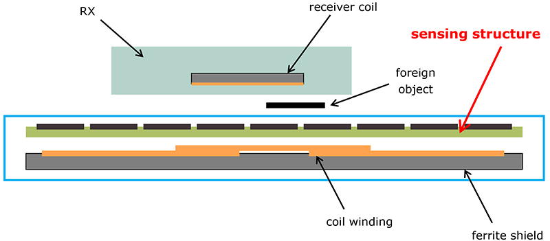
The standard FOD method relies on the large primary coil winding for detecting foreign objects, which reduces sensitivity and signal to noise ratio. Smaller objects are difficult to detect, due to the small impact on the magnetic field of the much larger primary coil. Existing transmitter solutions measure the parameters needed for the power delta calculation (voltage and current) at the DC side of the coil driver. This distorts the measurement when compared with the actual values at the coil, causing an inaccurate transmitter loss calculation.

An improved FOD method uses smaller sensing elements to detect small foreign objects, which greatly increases sensitivity and signal to noise ratio. This approach improves accuracy of the coil quality factor measurement to ensure even the smallest foreign objects are detected at the start of charging, even outside of the primary coil area.

Flexible software-based architecture

Rather than rely on an application specific IC for protocol and power delivery, the strength of the Infineon wireless charging solution lies in its modular software-based architecture.  Wireless charging is continually evolving, as standards mature, and new products and applications are introduced to the market. The high software content of the solution allows a common hardware architecture to be used across several reference designs, with each reference design flexible enough to support several types of applications.  In addition, future changes to the wireless charging standards can be supported by a software upgrade, which creates a future-proof product design that can span multiple generations.


Whitepaper Wireless charging: advanced technology delivers consumer convenience

The software is responsible for directing all major wireless charging functions in the system.  A fully digital demodulation scheme provides greater sensitivity for decoding communication in times of weak coil coupling due to misalignment, and also ensures the highest level of interoperability with legacy receivers.  Next-generation parameter measurement techniques ensure the highest accuracy for optimal power delivery and FOD. Precise control of frequency, duty cycle and voltage provide the correct level of rectified power at the receiver, and two-way communication on some systems enables smart charging with two-way authentication. Underneath the higher-level functions, a real-time engine keeps track of every aspect of transmitter operation from input supply, to efficiency, to thermal performance and makes adjustments as required. Finally, a self-calibration step during initial transmitter power-up provides a predictable baseline performance ensuring each product meets the requirements of the application.

AURIX and XMCsupport wireless charging

Efficient and easy-to-use wireless charging for smartphones, wearables, medical and industrial devices is supported by the AURIX and XMC microcontroller families. Flexible chip sets for high performance including software IP for smart and safe wireless charging applications are available. Working with a systems solution partner, Infineon provides reference designs for both inductive and resonant wireless charging solutions: for on-the-go charging, whether in the car, at home or in public places.

The controller works seamlessly with power devices from Infineon to provide a complete charging solution. Optimized voltage regulators, drivers and power MOSFETs enable high efficiency power conversion, while network ICs serve for reliable communication according to highest automotive standards. The complete solutions support future changes with a software update. An enhanced power stage architecture improves EMI performance 10-15 dB over existing solutions on the market. A newly developed supplemental FOD system provides enhanced detection accuracy to meet critical customer safety requirements.

XMC microcontrollers provide ultra fast charging.
XMC microcontrollers provide a powerful and cost-effective platform from a fast charge smartphone, to a 20 W robot, up to a 60 W drone and beyond.

AURIX microcontrollers help the next-generation in-cabin wireless charging systems meet strict automotive safety, security, environmental and regulatory requirements. On the other hand, XMC microcontrollers provide a powerful and cost-effective platform. The scalable architecture can support everything from a fast charge Smartphone, to a 20 W robot, up to a 60 W drone and beyond. Paired with related power products, like MOSFETs and driver ICs, this system can provide full power wireless charging without complicated thermal management, often achieving charging rates equivalent to wired charging.

Reference designs

Infineon provides complete reference designs that support many of the current and next-generation wireless charging applications. These reference designs include the hardware design, bill of materials, example PCB layout and all the documentation required to integrate wireless charging into the customer’s product.

The XMC based 2.5 W low-power solution is the industry’s lowest cost resonant wireless charger. By using a higher frequency (6.78 MHz), very small coils can be employed in a variety of form factors, with no regard to nearby metallic objects. These benefits make the technology ideal for charging wearables, headphones, smart clothing and other connected IoT applications.

An inductive Smartphone/handheld solution provides 15 W charging and existing standards, including fast charge smart phones with high efficiency charging without special thermal management. It achieves charging rates equivalent to wired charging and supports custom charging profiles and industry standards on the same hardware.

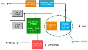
An inductive automotive in-cabin solution supports 15W charging and all existing standards, including fast charge smart phones. The solution allows the charging of two devices by using a single controller. This single AURIX controller supports wireless charging, system application, CAN and external NFC interface. Built in security functionality meets latest automotive requirements.

A 60 W inductive wireless charging solution for various devices provides industry’s highest power levels on the smallest coils. It offers high efficiency charging up to 60 W without exotic thermal management. The solution is backward-compatible with Smartphone charging standards (5 W or 15 W) and fast charge devices. Typical applications are power tools, laptops, robots, small appliances, drones, handheld terminals, medical instruments, industrial automation.

Dedicated microcontrollers for wireless charging

The AURIX wireless power controllers like the SAK-TC212S-8F133SC helps the next-generation in-cabin wireless charging systems meet strict automotive safety, security, environmental and regulatory requirements, while still enabling industry-leading charging performance and efficiency. This controller works seamlessly with Infineon’s power and interface devices to provide a complete charging solution for smart phones and other connected devices

Infineon’s wireless power controller XMC751SC-Q040 and the other members of this series based on the ARM Cortex-M0 core works seamlessly with Infineon’s power devices in a scalable and cost-effective architecture to provide a complete charging solution for everything from a fast charge Smartphone, to a 20 W robot, to a 60 W drone and beyond.